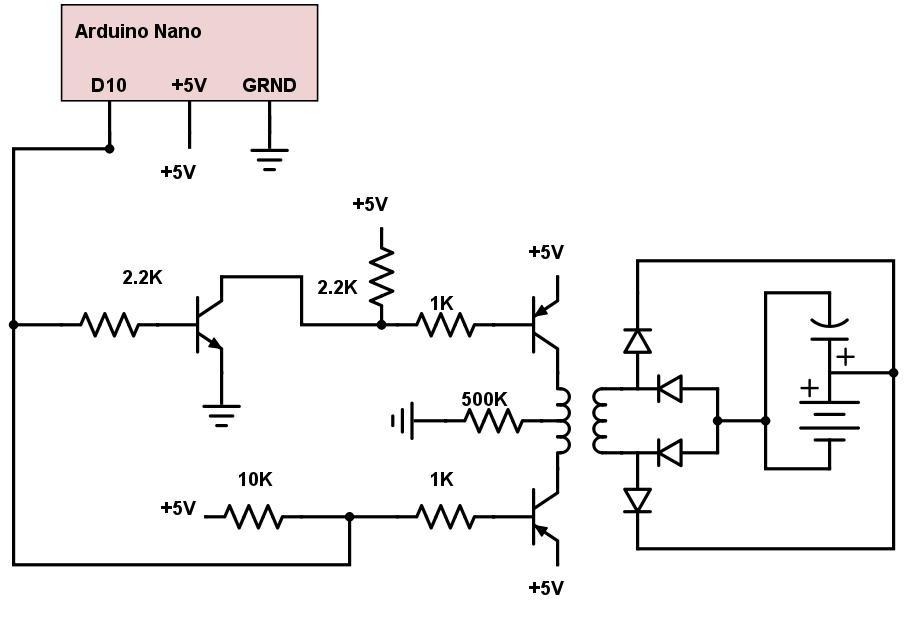
First, to assemble an inductive coupler you simply need to follow the schematic that was designed specifically for this project. It is displayed below:
This circuit will be using a NPN transistor to invert a signal so it can send it to a PNP transistor to give one side of the center tapped coil an inverted signal from what the other PNP transistor is giving it. This will create AC. The pulsing back and forth will be switching the magnetic fields poles and will pull the electrons in any nearby coils creating AC. This is then converted to DC with a rectifier using four diodes and a capacitor to smooth out the current flow. This then can be hooked up to your battery and can charge it.
Below is a video of the first version being tested using an oscilloscope.
Observations from Test: No noise, generated a little over four volts, pulses did not last very long, ended up being small, cheap materials, user friendly/not complicated.